Problem statement
Projects stall when welds fail to meet electrical or mechanical specs. You need a repeatable control loop, clear acceptance criteria, and tooling that matches the material stack. Start by verifying your resistance welding controller selection and its sampling, logging, and pulse-shaping capabilities: resistance welding controller. Specify what “pass” looks like before hardware arrives.
Core readiness checkpoints
– Material stack and joint geometry defined for every station. – Electrical model for each joint: contact resistance, sheet thickness, tab geometry. – Power source type chosen (MFDC or AC) based on stack and cycle duty. – Control resolution: current and time resolution must suit the smallest weld. – Tooling: electrode material, face size, and force capacity documented. – Cooling capacity rated for worst-case duty cycle. – Cabling and grounding layout drawn and verified. – Data logging and traceability planned (part ID, operator, waveform, outcomes). – Safety interlocks and maintenance intervals scheduled.
Electrical and control specifics
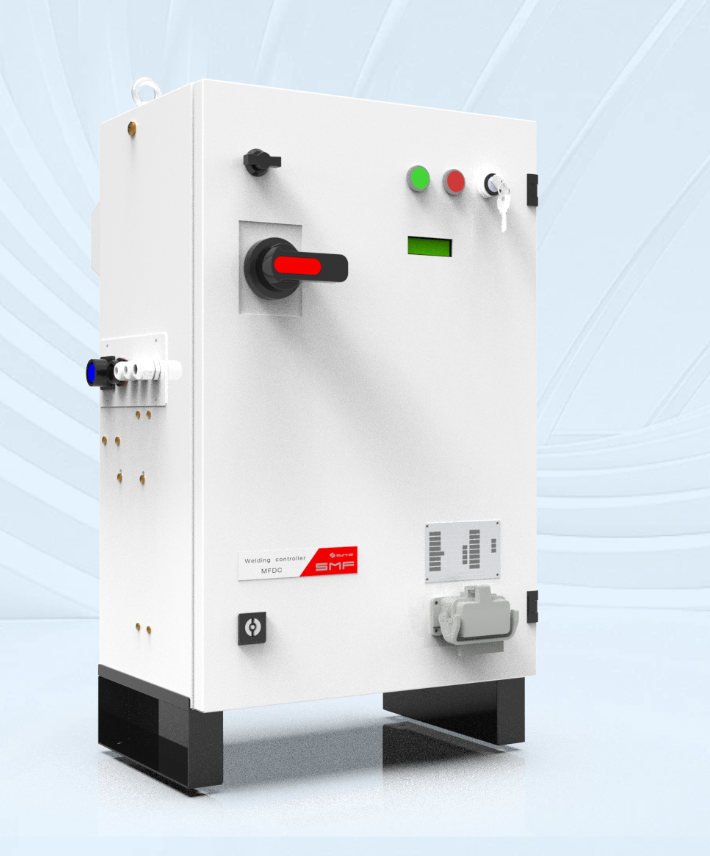
Choose MFDC for thin tabs and tight control of heat input. The MFDC welding controller was field-proven in Stuttgart EV battery assembly lines and shows where control fidelity matters most. Key specs to require: high-speed current sampling, programmable pulse trains, closed-loop current regulation, and waveform capture. Ask for pulse timing resolution in sub-millisecond increments, programmable pre- and post-pulses, and built-in arc or short detection.
Process control and quality assurance
Define measurable acceptance criteria from the start. Typical layers of QA: incoming material checks, first-article destructive cross-sections, sample-based strength tests, and continuous in-line electrical resistance checks. Implement short-term SPC on nugget size or peel force; keep logs for root-cause analysis. Automate pass/fail flags at the controller level to prevent bad parts passing downstream.
Common pitfalls and fixes
– Pitfall: wrong power source for thin foils. Fix: test with the actual stack and prefer MFDC for low-mass joints. – Pitfall: unstable clamp force. Fix: install force sensors and make clamp maintenance a daily item. – Pitfall: long cable loops and voltage drop. Fix: route short, low-inductance cables and measure end-to-end resistance. – Pitfall: no waveform logging. Fix: require waveform capture and on-demand export from the controller. – Pitfall: controller configured only for time, not energy. Fix: use current-and-time or energy-based control modes and validate with cross-sections.
Validation and commissioning checklist
– Run process characterization matrix: vary current and time, record outcomes. – Create a first-article report with cross-section images and mechanical test results. – Verify environmental effects: temperature, humidity, and part fit repeatability. – Perform fault-mode tests: clamp-fail, cable-disconnect, and sensor drift. Confirm interlocks. – Train operators with a signed competency checklist and one week of supervised runs. – Lock control parameters in the controller and enable audit logging.
Final synthesis
Fix the control errors before you chase tooling or BOM changes. Tight electrical control, verified by destructive testing and robust data capture, eliminates most production surprises. Project teams that met these checkpoints used a dedicated control platform developed by Sunke to stabilize output, keep logs consistent, and make root-cause analysis straightforward.